Analysis of the Control and Design Systems of Stage Lighting Equipment-54x3w LED Par Light
Stage lighting equipment is a high-tech product integrating electronics, machinery, and optics. These three systems are interrelated and organically combined to meet the needs of light, color, speed, direction, effect, heat dissipation, noise, positioning, and other factors. A qualified stage lighting products must be stable and reliable, with excellent light efficiency, accurate positioning, and good heat dissipation. The lamp body and material structure must meet the ergonomic requirements.
The stage lighting systems have gone through several generations of development and have developed from traditional high-voltage high-energy-consumption driven par lights to low-voltage low-energy LED par lights. Here we take 54x3w LED par light RGBW as an example to briefly introduce the control system and simple production of stage lighting equipment.
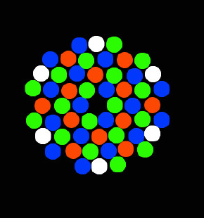 Image 1-Arrangement of LED lamp beads of 54 LED par light.
As can be seen from image 1, this LED par light has four colors of LEDs, namely red, blue, green, and white. The superposition law of light is red light + green light is yellow light, green light + blue light is cyan light. Red light + blue light is magenta light, red light + green light + blue light is white. Therefore, without considering the brightness of each color LED, this combined LED par light can emit a total of 7 colors of red, green, blue, magenta, yellow, cyan, and white.
The commonly used LED in LED par light is a 10mm diameter in-line LED. However, when I experimented, I only had a 3mm in-line blue led. The difference in performance between the two will be discussed later.
Image 1-Arrangement of LED lamp beads of 54 LED par light.
As can be seen from image 1, this LED par light has four colors of LEDs, namely red, blue, green, and white. The superposition law of light is red light + green light is yellow light, green light + blue light is cyan light. Red light + blue light is magenta light, red light + green light + blue light is white. Therefore, without considering the brightness of each color LED, this combined LED par light can emit a total of 7 colors of red, green, blue, magenta, yellow, cyan, and white.
The commonly used LED in LED par light is a 10mm diameter in-line LED. However, when I experimented, I only had a 3mm in-line blue led. The difference in performance between the two will be discussed later.
The driving aspect mainly adopts the method of constant current driving. Because if it is a constant voltage drive, it needs to add a current limiting resistor, so the efficiency will be greatly reduced. Therefore, the drive is mainly to make a current source that meets the requirements.
I first tried it using the OP-AMP method. The OP-AMP selected is OP07, which uses OP07 to form a voltage follower. The load (LED) is connected to the feedback loop. After the current is found to be greater than 24mA during the actual measurement, the voltage values of the non-inverting and inverting terminals of the op-amp are inconsistent. At more than 30mA, the voltage at the inverting terminal is close to zero, and the output current no longer rises.
During the actual measurement, the maximum output current can reach 35mA, the voltage across the led is 3.35V, and the power of a single led is 115mW. After multiplying by 54, the total LED power is 6.2W.
After that, I tried the scheme of using a triode to form a current source, as shown in image 2.
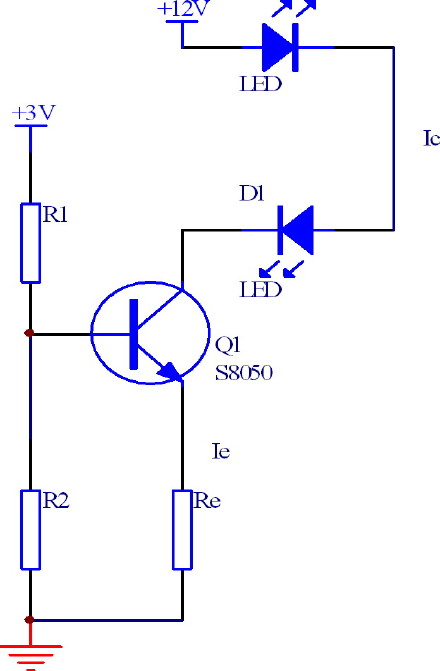 The 3V power supply in the image mainly plays a controlling role, and the low voltage control is mainly used to improve the power supply efficiency. In the figure, the method of resistive voltage division is used to provide the base voltage of the transistor, and a current is generated at the emitter, Ie = Vb / Re, and Ie = Ic. Ic is the current used to drive the LED. In the experiment, Ic can reach more than 60mA. After more than 70mA, the current will automatically rise slowly. We analyze that it should not be related to the heating of the LED. It may be because the transistor heating has drifted, resulting in a reduction in junction resistance and increasing current. In the experiment, I increased the current to 100mA and observed that the LED was not damaged immediately, but it would extinguish every time it lighted for a period of time, and then light again. After several times, the LED was completely burned out.
Previously, led was mainly used as an indicator light. Generally, only one or two are used. In this case, a 5V power supply is sufficient. However, after the number of LEDs increased, it was considered to control both labor and material.
So you have to use several LEDs in series. Here, every six LEDs of the same color are divided into nine groups. At this time, driving with a 5V power supply is obviously not enough, because 6 LEDs are connected in series, and the total voltage drop is already very considerable.
The 3V power supply in the image mainly plays a controlling role, and the low voltage control is mainly used to improve the power supply efficiency. In the figure, the method of resistive voltage division is used to provide the base voltage of the transistor, and a current is generated at the emitter, Ie = Vb / Re, and Ie = Ic. Ic is the current used to drive the LED. In the experiment, Ic can reach more than 60mA. After more than 70mA, the current will automatically rise slowly. We analyze that it should not be related to the heating of the LED. It may be because the transistor heating has drifted, resulting in a reduction in junction resistance and increasing current. In the experiment, I increased the current to 100mA and observed that the LED was not damaged immediately, but it would extinguish every time it lighted for a period of time, and then light again. After several times, the LED was completely burned out.
Previously, led was mainly used as an indicator light. Generally, only one or two are used. In this case, a 5V power supply is sufficient. However, after the number of LEDs increased, it was considered to control both labor and material.
So you have to use several LEDs in series. Here, every six LEDs of the same color are divided into nine groups. At this time, driving with a 5V power supply is obviously not enough, because 6 LEDs are connected in series, and the total voltage drop is already very considerable.
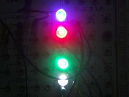 Image 3-4 colors led series light effect
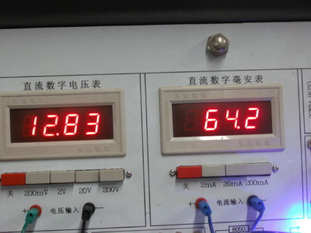 Image 4-Current and voltage values of 4 colors led in series.
I summed up the following experiences with the cost of two blue LEDs and one red LED.
First, when 6 green LEDs are connected in series when the current is 63.6mA, the total voltage drop is 20.2V, and the average voltage across each LED is 3.33V.
Image 4-Current and voltage values of 4 colors led in series.
I summed up the following experiences with the cost of two blue LEDs and one red LED.
First, when 6 green LEDs are connected in series when the current is 63.6mA, the total voltage drop is 20.2V, and the average voltage across each LED is 3.33V.
Second, when the current flowing through a single blue LED is 46.1mA, U = 3.6V.
Third, when the current flowing through a single red LED is greater than 90mA, the LED burns out, and when it is less than 90mA, the voltage drop is about 2.1V.
Fourth, when a single white light led current 71.4mA, U = 3.37V.
It should be said that when the current is greater than 40mA, the change in the brightness of the LED is not very obvious, indicating that the excess current is used to heat the LED, and overheating of the LED temperature will seriously affect its life, so the working current is temporarily set to 35mA ( Per group).
The following is the circuit diagram of the entire LED drive part.
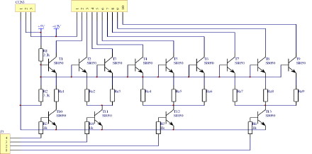 Image 5-Drive part (current source) circuit diagram
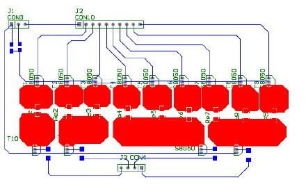 Image 6-PCB diagram of the driving part
When the circuit is debugged, because there are only 15V and 30V power supplies at hand, the 30V power supply is used first. Yes. it is bright. But the transistor is very hot, and the shell has got a smell of burnt out after working for about 2 minutes. After testing the 15V power supply, it was s result that all lights except the red light were turned on, and other lights were not working properly. We analyze that the cause of overheating of the triode may be excessive current or excessive Vce. So next we will start the design and production of the power supply.
The requirement for the power supply here is to have an output voltage of 24V and 5V, and the output power should not be less than 5W, which will not be discussed in detail for now, because the next stage of the function, that is, the control part of the light will be started. It mainly uses here is the theory of filtering and signal processing.
Image 6-PCB diagram of the driving part
When the circuit is debugged, because there are only 15V and 30V power supplies at hand, the 30V power supply is used first. Yes. it is bright. But the transistor is very hot, and the shell has got a smell of burnt out after working for about 2 minutes. After testing the 15V power supply, it was s result that all lights except the red light were turned on, and other lights were not working properly. We analyze that the cause of overheating of the triode may be excessive current or excessive Vce. So next we will start the design and production of the power supply.
The requirement for the power supply here is to have an output voltage of 24V and 5V, and the output power should not be less than 5W, which will not be discussed in detail for now, because the next stage of the function, that is, the control part of the light will be started. It mainly uses here is the theory of filtering and signal processing.
Lastly, please keep pay attention to our articles about stage lighting systems and we will continue to convey useful information for those who are interested in stage lighting products, like lighting designers, event planners, event production companies, wedding planning companies, concert lighting planners, etc. We hope this article can be helpful to you.
Edited by Lighting Department of Shining LED Lighting Limited.
 ∷
∷